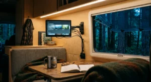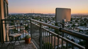
You can route free over-the-air television to four bedroom TV jacks using the coaxial cables already inside your walls. Ditching pay-TV saves the average household over $100 per month without sacrificing local news or live sports.
Most homeowners fail because passive 4-way splitters cut antenna signal strength by more than 75 percent, causing digital pixelation and missing channels.
This guide calculates your exact decibel loss budget and shows why replacing passive splitters with an active unity-gain distribution amplifier guarantees flawless reception on every screen.
Auditing Your Existing Coaxial Cable Splitter Setup
Before buying new hardware, you must map your home’s legacy coaxial network. Most suburban homes built after 1990 feature a central distribution box located in the basement, garage, or outside wall.
This enclosure connects the incoming street feed to individual bedroom wall plates. The practice of cord-cutting—canceling traditional cable or satellite TV in favor of streaming services and free antenna broadcasts—requires isolating these cables from the pay-TV provider.
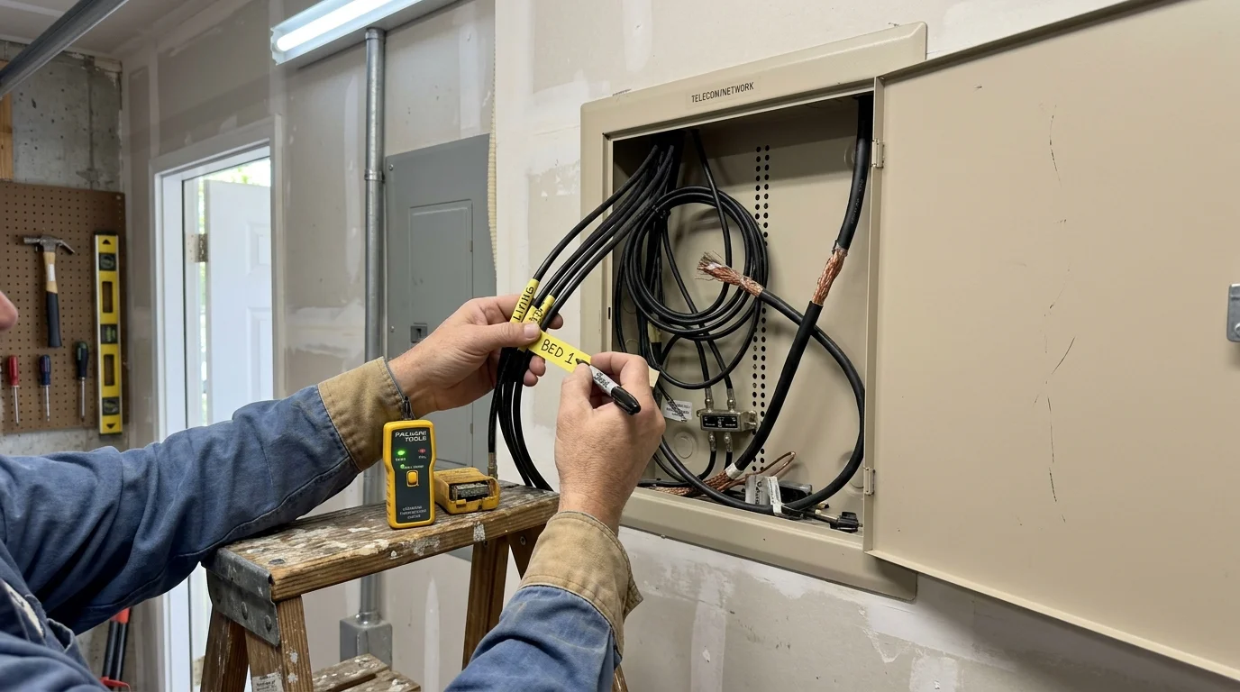
Open this exterior junction box or interior panel to locate the primary splitter. You will see a single input line coming from the street and multiple output lines feeding your living areas.
You must disconnect the main service line entering from the street immediately. Leaving the utility line attached introduces electrical ground loops and allows rogue antenna frequencies to leak into the neighborhood broadband grid.
Inspect the coaxial cable jacket markings carefully. Older homes often contain RG-59 cabling, whereas newer builds use standard RG-6 coax.
RG-59 cable features a thinner copper conductor and exhibits severe high-frequency signal loss over distances exceeding 50 feet. RG-6 coaxial cable provides superior shielding and thicker 18 AWG center conductors, making it the required standard for multi-room digital broadcast television.
According to consumer research from Cord Cutters News, repurposing existing in-wall RG-6 lines saves homeowners hundreds of dollars compared to running new exterior lines.
Label each cable with masking tape before unscrewing any connectors. A basic battery-operated coax continuity tester helps you trace which line feeds each specific bedroom.
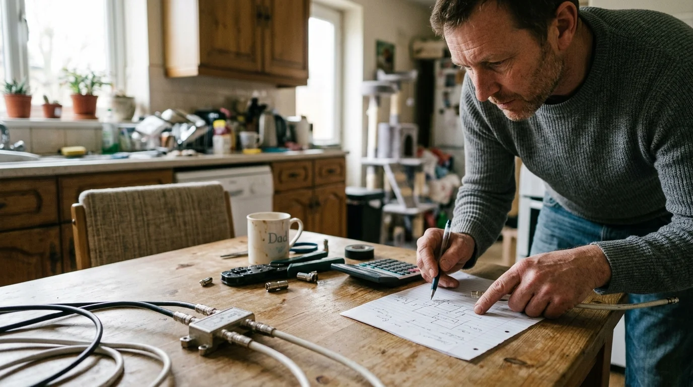
Calculating Coaxial Signal Loss Across Four Rooms
Digital broadcast television operates on strict radio frequency signal thresholds measured in decibel millivolts (dBmV). Tuners require signal levels between -12 dBmV and +15 dBmV at the wall jack to display a stable picture.
If your signal drops below -12 dBmV, your screen will experience macroblocking, audio squeals, or a complete loss of signal. This sudden drop from perfect reception to a black screen is known as the digital cliff effect.
Understanding antenna coax splitter signal loss prevents you from assembling a system that fails during bad weather. Signal degradation accumulates across three distinct areas: antenna transmission line distance, passive splitter attenuation, and interior room run lengths.
Standard RG-6 coaxial cable loses approximately 5.6 dB of signal strength per 100 feet at UHF frequencies around 600 MHz. Connectors and wall barrel jacks contribute an additional 0.5 dB of insertion loss at each connection point.
A standard passive 4-way balanced splitter divides incoming RF energy equally among four output ports. Physics dictates that splitting an electrical signal four ways introduces a mandatory insertion loss of 7.0 dB to 7.5 dB per port.
Consider this realistic suburban scenario: your attic antenna captures an initial signal of +10 dBmV from a local broadcast tower located 25 miles away.
The 40-foot RG-6 cable running from the attic to your central basement splitter drops the signal by 2.2 dB. The passive 4-way splitter immediately strips away another 7.4 dB of signal strength.
The remaining signal leaving each splitter port measures just +0.4 dBmV before traveling toward the bedrooms. A 60-foot run to the upstairs primary bedroom introduces an additional 3.4 dB of cable loss, plus 1.0 dB across the wall plate and patch cord.
The final signal reaching your television tuner drops to -4.0 dBmV. While this figure technically sits above the absolute failure floor, atmospheric changes or wind-blown trees will push the channel past the digital cliff.
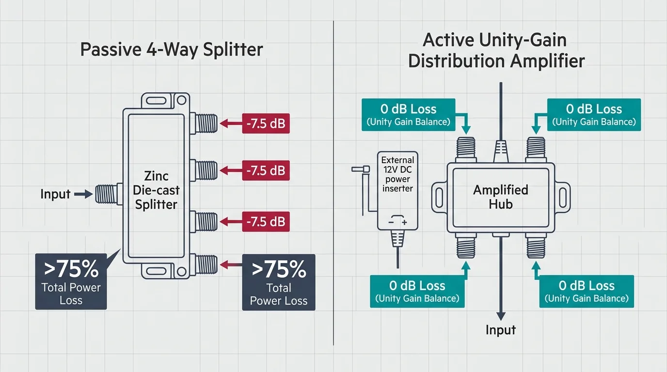
Passive 4-Way Splitters vs. Active Distribution Amplifiers
Passive splitters rely entirely on the original signal gathered by your antenna elements. They contain internal transformers that cut signal voltage across every port, creating weak reception on long cable runs.
A distribution amplifier for 4 TVs solves this problem by using an internal electrical circuit to restore signal strength. Unlike basic inline preamplifiers, a distribution amplifier mounts directly at your multi-switch location to drive multiple downstream tuners.
“Installing a unity-gain distribution amplifier replaces the natural 7.5 dB loss of a 4-way split, delivering the exact signal level captured by your antenna to every connected room.” — Antenna Systems Specialist
Most 4-room homes benefit most from a zero-loss or unity-gain distribution amplifier. A unity-gain unit provides approximately +7.5 dB of internal amplification to cancel out the natural loss of the 4-way split.
This design delivers a 0 dB net gain to each output port. As a result, each television receives the exact same signal level present at the amplifier’s input connector.
You must avoid ultra-high-gain distribution amplifiers offering +15 dB to +20 dB of boost unless your cable runs exceed 150 feet. Overdriving a digital TV tuner creates front-end overload, generating the identical pixelation and dropout symptoms caused by weak signals.
As documented by the FCC Consumer Guide, digital tuners require clean signal-to-noise ratios rather than raw, distorted amplification.
| Hardware Type | Port Signal Loss/Gain | Noise Figure | Power Consumption | Recommended Coax Length | Overload Risk |
|---|---|---|---|---|---|
| Passive 4-Way Splitter | -7.2 dB to -7.5 dB | 0 dB (Passive) | 0 Watts | Under 30 feet | None |
| 4-Port Unity-Gain Amplifier | 0 dB to +1.0 dB | 2.5 dB to 3.5 dB | 3 to 5 Watts | 30 to 100 feet | Very Low |
| High-Gain Distribution Amp (+12 dB) | +11.5 dB to +12.5 dB | 3.0 dB to 4.5 dB | 6 to 10 Watts | Over 100 feet | Moderate to High |
Choose an amplifier featuring a low noise figure, ideally below 3.5 dB. Amplifiers with high noise figures introduce electrical hiss that degrades signal quality even while increasing raw decibel levels.
Reputable models such as the Channel Master CM-3414 or PCT-MA2-4P include bypass sealing and heavy zinc housings. These units withstand temperature fluctuations when mounted inside unconditioned crawlspaces or attics.
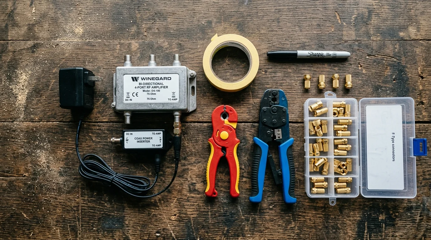
Required Equipment and Cost Breakdown
Executing whole house ota antenna distribution requires specific hardware designed for 75-ohm RF distribution. Investing in proper installation gear guarantees decades of maintenance-free broadcast reception.
- Directional or multi-directional attic antenna: $60 to $120
- 4-port active distribution amplifier (unity-gain): $35 to $55
- 50-foot solid copper RG-6 coax feedline: $20 to $30
- 75-ohm F-connector termination caps (pack of 10): $6
- Coaxial cable compression tool and stripper: $25
- Coaxial ground block and 10 AWG copper wire: $12
Your total one-time hardware investment will range between $158 and $248. Compare this expenditure against the ongoing cost of subscription television.
The average basic cable package costs $115 per month once regional sports fees and box rentals are added. Converting to an attic antenna setup pays for itself entirely within seven to ten weeks.
Once your antenna feeds live broadcast networks to all four rooms, you can complement your setup with streaming services. Streaming involves watching video content over the internet instead of relying on cable lines or satellite dishes.
You can connect an inexpensive streaming device—such as a Roku Express or Amazon Fire TV Stick—to older screens. Alternatively, you can use the operating software built directly into a modern smart TV.
Viewers can mix ad-supported plans that show commercials for a lower price with ad-free subscriptions that eliminate marketing interruptions entirely. You can also deploy an over-the-air DVR, which lets you record and pause live antenna broadcasts without recurring monthly hardware rental fees.
Broadband television expands your options further with on-demand catalogs, allowing you to watch movies and series whenever you choose. Many cord-cutters maintain an ultra-fast home internet connection for under $60 per month while receiving local channels completely free.
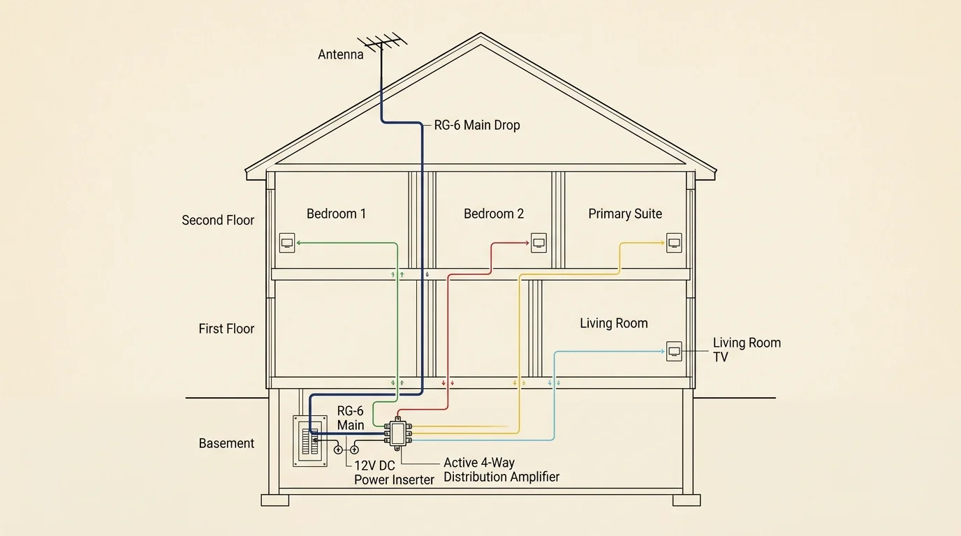
Step-by-Step Attic Antenna and Coax Integration
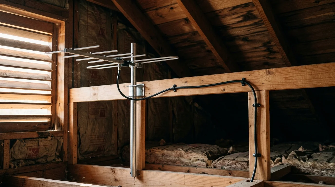
Begin by assembling your antenna inside your attic space. Attics protect antennas from wind, ice, and ultraviolet degradation, though roofing materials decrease overall signal strength by 30 to 50 percent compared to rooftop mounts.
Position the antenna away from metal HVAC air ducts, furnace blowers, and electrical wiring runs. Metal surfaces reflect incoming radio waves and create multipath distortion that confuses digital tuners.
Aim your antenna directly toward your local broadcast transmission towers. You can verify the exact compass bearings for your local broadcast cluster using the official FCC reception maps.
Connect your main RG-6 feedline cable to the antenna’s 75-ohm output terminal. Run this feedline down into your central home distribution cabinet through an interior wall cavity, closet space, or plumbing chase.
Locate the old passive splitter inside your central junction enclosure. Unscrew the incoming cable service line and move it completely outside the box to prevent accidental connections.
Mount your 4-port distribution amplifier securely against the backboard of the junction enclosure. Connect the feedline coming from your attic antenna directly into the port marked “RF IN” on the amplifier.
Connect the four individual room cables leading to your bedrooms into the amplifier ports labeled “RF OUT.” Tighten each connection finger-tight, then apply a quarter-turn with a 7/16-inch open-end wrench to secure the ground shield.
Power your distribution amplifier using its included AC adapter. Most units support remote power feeding via a coaxial power inserter if an electrical outlet is unavailable inside your junction box.
If you choose remote powering, screw the power injector onto room line number one between the wall plate and your television set. The low-voltage direct current travels upward through the coaxial copper core to power the central amplifier unit.
Screw 75-ohm F-connector termination caps onto any unused amplifier output ports. Open ports act as radio antennas, picking up electromagnetic interference and reflecting unused energy back into your active television lines.
Navigate to the settings menu on each of your four televisions. Switch your tuner input setting from “Cable” to “Air” or “Antenna,” and run an automated channel scan on each screen.
Canceling Cable TV and Managing Leased Equipment
With four rooms receiving crystal-clear broadcast signals, you are ready to terminate your pay-TV subscription. Careful planning during this transition protects you against surprise billing fees and equipment penalties.
Contact your cable provider—such as Comcast Xfinity, Spectrum, or Cox—and state clearly that you wish to cancel TV service while retaining your standalone home internet tier. Insist on speaking directly with the customer retention department to avoid service transfer delays.
Verify whether your current subscription carries an active contract term. Most standard agreements convert to month-to-month service after 12 or 24 months, exempting you from early termination fees.
Schedule your cancellation date to align with the final day of your current billing cycle. Many major cable operators no longer prorate partial-month television bills when customers cancel mid-cycle.
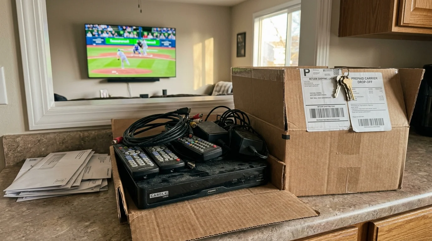
Gather every piece of leased equipment from your home before visiting the provider’s retail center. This inventory includes primary cable boxes, digital adapters, power transformers, and voice remote controls.
Independent product evaluations from Consumer Reports consistently warn consumers about unreturned equipment fees. Cable companies frequently charge between $100 and $250 per missing set-top box.
Drop off the hardware directly at an authorized retail storefront rather than placing it in an unmonitored drop box. Request a physical, printed receipt itemizing the exact serial number of every returned device.
Store this receipt in your financial records for at least twelve months. Erroneous collections for returned cable boxes remain one of the most common billing disputes reported across the telecom industry.
Troubleshooting Channel Loss and Signal Dropouts
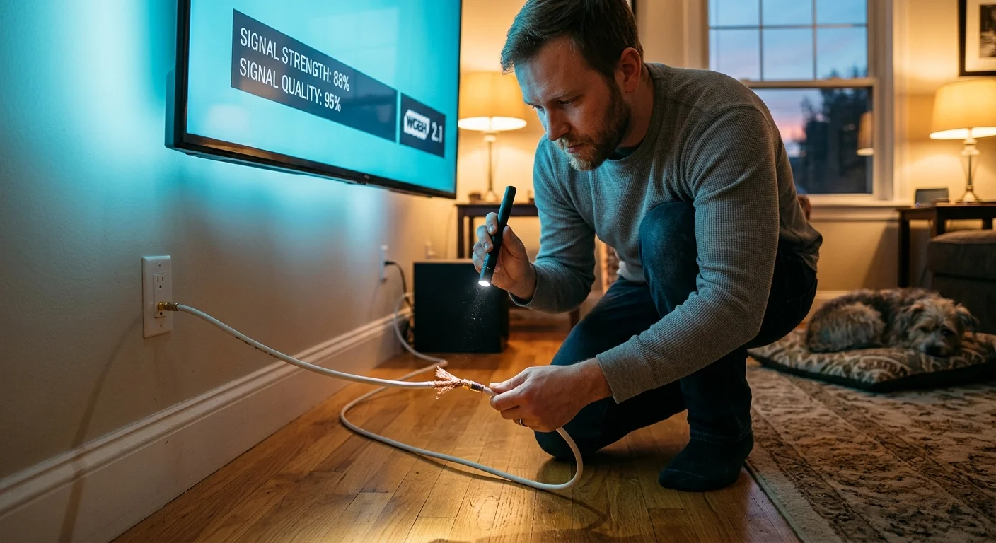
If one television displays pixelated artifacts while other rooms perform flawlessly, check the integrity of your coaxial wall connectors. Low-quality screw-on or crimp-style F-connectors often experience braid slippage that introduces severe signal loss.
Replace outdated twist-on connectors with professional compression fittings. Compression connectors feature a 360-degree internal brass sleeve that seals out atmospheric moisture and guarantees continuous ground continuity.
Ensure that radiant barrier roof decking is not obstructing your attic antenna. Plywood backed with metallic foil acts as a virtual RF shield, blocking almost all high-frequency UHF television transmissions.
If your attic contains a radiant barrier, you must relocate the antenna to a gable wall window or move the assembly outdoors. Even high-end distribution amplifiers cannot amplify an antenna signal that has been blocked by metallic foil barriers.
Nearby cellular telephone towers can also disrupt digital television frequencies. Wireless carriers utilize 4G LTE and 5G cellular frequencies directly adjacent to broadcast television channel 36.
High-power cell tower transmissions overload distribution amplifiers, creating intermittent digital dropouts and picture freezing. Installing an inline 5G/LTE filter between your antenna feedline and the distribution amplifier suppresses these stray signals.
Hardware testing published by Wirecutter highlights that inline low-pass filters eliminate wireless network interference without degrading lower VHF or UHF broadcast channels.
Inspect your distribution system for pinched coaxial lines inside wall cavities. A sharp bend exceeding the manufacturer’s minimum bend radius crushes the internal polyethylene dielectric, altering cable impedance and triggering severe signal reflections.
Frequently Asked Questions
Can I send internet and antenna signals through the same coaxial cable?
No, you should never combine cable broadband signals and over-the-air antenna frequencies on the same coaxial line. Cable internet relies on DOCSIS frequencies that overlap directly with VHF and UHF broadcast television bands, causing severe modem disconnects and TV reception failure.
Do I need a separate digital converter box for each of my four televisions?
You do not need an external converter box if your televisions were manufactured after 2007. Federal law mandates that all modern sets include a built-in ATSC 1.0 digital tuner capable of decoding digital broadcast signals directly through the coaxial antenna input.
Why do some channels disappear at night while working during the day?
Atmospheric temperature inversions and environmental interference alter digital signal propagation between transmission towers and your attic antenna. If your daytime signal sits right along the digital cliff edge, minor nighttime atmospheric shifts will push reception below the tuner threshold.
Can I leave unused ports open on my distribution amplifier?
You must never leave active amplifier distribution ports open and unterminated. Unterminated ports act like small antennas that absorb interior electrical noise and cause radio frequency signal reflections, degrading the reception quality across your connected televisions.
Disclaimer: Cable and streaming prices vary by location and change frequently. The cost comparisons in this article are estimates based on typical pricing. Your actual savings will depend on your current cable package, internet costs, and which streaming services you choose.